Showing posts with label Huawei SDH. Show all posts

Wednesday, November 15, 2017

Huawei OSN3500 Cross-Connect Boards SXCSA

Application

The SXCSA is a super cross-connect and synchronous timing board apply to Huawei MSTP OSN3500. The SXCSA provides service grooming and clock input/output functions in the OptiX OSN system.
The cross-connect and synchronous timing board provides the other boards in the system with the timing information, converges and grooms services, communicates with the other boards in the system, and performs the configuration and management functions for the other boards in the system.

Position of the cross-connect and synchronous timing board in the system 


Working Principle and Signal Flow

Huawei SXCSA consists of the synchronous timing module, cross-connect module, communication and control module, and power module.

Functional block diagram of the SXCSA 

Synchronous Timing Module

The synchronous timing module uses the centralized timing allocation mode as the clock mode. The synchronous timing module also selects one clock source from reference clock sources as the reference clock for the timing module. The reference clock sources are from the line board, the tributary board, or the external synchronous clock source. The synchronous clock source and 2 Mbit/s or 2 MHz external synchronous clock source are then generated.
The precise 38 MHz oscillator ensures that the reference clock complies with ITU-T standards in free-run mode.
The SDH clock (SETS) can work in the following modes:
  • Lock mode
  • Hold-over mode
  • Free-run mode
When working in lock mode, the SETS extracts the clock from three types of timing signals:
  • Timing signal (T1) from the STM-N line
  • Timing signal (T2) from the PDH line
  • Reference signal (T3) from the external synchronous clock source (2 MHz or 2 Mbit/s)
The timing module outputs the following timing signals:
  • T0, system clock
  • T4, external timing output signal (2 Mbit/s or 2 MHz)

Cross-Connect Module

The cross-connect module consists of two parts:
  • SNCP module, which tests relative alarms and reports the alarms to the software to trigger the protection switching such as the SNCP switching and MSP switching.
  • Higher order and lower order cross-connect module, which performs the functions of higher order and lower order cross-connect units.

Communication and Control Module

The communication and control module is a sub-system provided by the pinch board. It consists of the CPU, register, Ethernet port, HDLC controller, FPGA loading controller, and bus driver. This module is connected to external circuits through buses to manage and configure other units of the boards.

Power Module

It converts the –48 V/–60 V power supply into the DC voltages that the modules of the board require.

Monday, September 18, 2017

What is the System Architecture of Huawei OTN OSN8800?


The OptiX OSN 8800 system uses the L0 + L1 + L2 architecture. Ethernet/MPLS-TP switching is implemented on Layer 2, ODUk/VC switching on Layer 1, and wavelength switching on Layer 0.

System architecture of the OptiX OSN 8800 (MS-OTN) 
System architecture of the OptiX OSN 8800 (OCS) ]

Functions of modules are as follows:
  • Optical-layer boards are classified into optical multiplexer and demultiplexer boards, optical add/drop multiplexing (OADM) boards, optical amplifier (OA) boards, optical supervisory channel (OSC) boards, optical spectrum analysis boards, optical variable attenuator boards, and optical power and dispersion equalization boards. These boards are intended to process optical-layer services, for example, to cross-connect wavelengths at the optical layer.
  • Electrical-layer boards such as OTU, tributary, and line boards like 40G TN54NS3 are used to process electrical-layer signals, and perform conversion between optical and electrical signals. The OptiX OSN 8800 uses a tributary-line-separate architecture, and a centralized cross-connect unit to flexibly groom electrical-layer signals at different granularities.
  • For OptiX OSN 8800, an universal line board is used to process electrical-layer signals and perform conversion between optical and electrical signals. In addition, an universal line board can work with a centralized cross-connect board to achieve hybrid transmission and fine-grained grooming of OTN, SDH, and packet services.
  • For OptiX OSN 8800, EoO, EoW, Ethernet over SDH (EoS), and packet boards have L2 processing capabilities. They can add, strip, and exchange MPLS or VLAN tags, learn MAC addresses, and forward packets. Only packet boards can add, strip, or exchange MPLS tags.
  • As the control center of the entire system, the system control and communication (TN52SCC) board cooperates with the network management system (NMS) to manage boards in the system and to implement inter-subrack communication.
  • The clock board provides system clock signals and frame header signals to each service board, and synchronizes the local system time with the upstream system time, achieving clock and time synchronization.
  • The power supply and fan systems with a redundancy protection design ensure highly-reliable equipment operation.
  • The auxiliary interface board provides functional ports such as clock/time input/output ports, management serial port, alarm output and cascading ports, and alarm input/output ports.
  • Inter-board communication and service cross-connections, clock synchronization, and power supplies are implemented using the backplane buses. Backplane buses include control and communication buses, clock buses, and power buses.


Sunday, August 20, 2017

Huawei OSN3500 Introduction

Positioning


Huawei OptiX OSN 3500 intelligent optical transmission system (the OptiX OSN 3500 for short) developed by Huawei is the next-generation intelligent optical transmission equipment.
Huawei OptiX OSN 3500 is of a "universal switch" architecture. That is, the OptiX OSN 3500 can be used in packet mode or in TDM mode. When used with the other equipment of Huawei, the OptiX OSN 3500 supports various networking applications, such as the pure packet mode application, hybrid networking application (overlay networking of the packet mode and TDM mode), and pure TDM mode application. By using a proper networking solution, the data service and conventional SDH service can be processed in the optimal manner.

Technology

The OptiX OSN 3500 transmits voice and data services on the same platform with high efficiency. It integrates the following technologies:
  • In packet mode, the OptiX OSN 3500 supports the following technologies:
    • Multiprotocol Label Switching (MPLS)
    • Multiprotocol Label Switching Transport Profile (MPLS-TP)
    • Pseudo Wire Edge to Edge Emulation (ETH PWE3)
    • TDM PWE3
    • ATM PWE3
  • In TDM mode, the OptiX OSN 3500 supports the following technologies:
    • Synchronous digital hierarchy (SDH)
    • Plesiochronous digital hierarchy (PDH)
    • Ethernet
    • Asynchronous transfer mode (ATM)
    • Storage area network (SAN)/Video
    • Wavelength division multiplexing (WDM)
    • Digital data network (DDN)
    • Pulse Code Modulation (PCM)
Exterior of the OptiX OSN 3500 

Network Application


As shown in Figure, the OptiX OSN 3500 is mainly used at the convergence layer and backbone layer of the metropolitan area network (MAN). The network application scenarios are described as follows:

  • In TDM networking, can be networked with the other OptiX transmission equipment (the OptiX OSN 9560, OptiX OSN 9500, OptiX OSN 7500 II, OptiX OSN 7500, OptiX OSN 3500 II, OptiX OSN 2500, OptiX OSN 1500, OptiX OSN 500, and OptiX OSN 550) to optimize the carrier's investment.
  • With the packet switching technology, can constitute a packet data transmission network with the other OptiX transmission equipment (the OptiX OSN 7500 II, OptiX OSN 7500, OptiX OSN 1500, OptiX OSN 500, OptiX OSN 550, OptiX PTN 910, OptiX PTN 950, OptiX PTN 1900, OptiX PTN 3900, and OptiX RTN 900) to meet the requirement for bearing IP services.
  • Can be flexibly networked with WDM equipment and Huawei Metro equipment.
  • Can transparently transmit services over third-party Layer 2 networks, allowing end-to-end configuration and management.

Friday, August 4, 2017

Generation and Detection of Alarms and Performance Events in the SDH Higher Order Signal Flow

The principle for locating fault is "line first, then tributary; higher order first, then lower
order".
Therefore, this section focuses only on the alarms and performance events generated between
the SDH interface and the cross-connect unit like Huawei GXCSA during maintenance. This section describes the signal flow and the procedure for handling each overhead byte by each module.

Alarm signals generated between the SDH interface and the cross-connect unit

Based on the positions of the various overhead byte processing in the STM-64, STM-16, STM-4, STM-1 frame, the overhead
bytes are classified into four modules:
Regenerator section overheads
Multiplex section overheads
Higher order path overheads
Lower order path overheads
If a fault occurs in the first two modules, it affects all the higher order paths. If a fault occurs in
the overhead bytes of a higher order path, however, it affects only this higher order path and its
lower order paths.
The following sections describe the signal flow and the processing of each overhead byte.

Downlink Signal Flow
In the higher order downstream signal flow, overhead bytes are extracted and terminated.
Frame Synchronizer and Regenerator Section Overhead Processor

Uplink Signal Flow
The overhead bytes are extracted and then terminated in the downlink signal flow of the higher
order path. Overhead bytes are generated and alarm signals are returned to the opposite NE in
the uplink signal flow of the higher order path.

Sunday, July 9, 2017

How to Plan Orderwire Phone Interfaces on Huawei Optix OSN2500?

Capability of Supporting Orderwire Phone Interfaces

The capability of supporting orderwire phone interfaces is defined.
The Q1SEI board of the Huawei OptiX OSN 2500 provides one orderwire phone interface, two NNI
voice interfaces and two NNI signaling interfaces. The five interfaces are all of the RJ-45 type.

Planning Principles

The principles for planning the orderwire phone interfaces are defined.
Adhere to the following principles when planning orderwire phone interfaces:


  • Make sure that the orderwire signaling is compatible in the entire network.
  • Make sure the orderwire phone number of each node is of the same length. It is recommended that the orderwire phone number be set as four characters.
  • Set the orderwire phone number in the format: subnet number (one character) + user number (three characters).
  • Make sure that the conference phone numbers in the entire network are the same and the number should be larger than the orderwire phone number. It is recommended that the conference phone number be set to 9999.
  • Make sure that all orderwire phone numbers in the entire network, except the conference phone number, are unique.
  • Make sure that the dial-up scheme of the orderwire phone of each node is dual-tone multifrequency.
  • Make sure the call waiting time of each node is the same. If less than 30 nodes are present in the network, set the call waiting time to 5s. If more than 30 nodes are present in the network, set the call waiting time to 9s.
  • The orderwire phone number should increase as the node ID increases.
  • Consider the possibility of howl in the orderwire loop. Release the loop to solve the problem of howl in the conference phone. The loop is automatically released, if an OptiX OSN 2500 system is networked with other OptiX OSN 2500 systems, or with Huawei OptiX OSN 7500, OptiX OSN 3500, OptiX OSN 3500T, OptiX OSN 2500REG and the OptiX OSN 1500. If the OptiX OSN 2500 is networked with other equipment, manually release the loop.
  • If no optical path is available between two nodes, which, however, require orderwire communication, use the orderwire NNI connection for the orderwire communication. Use Voice 1 or Voice 2 as the voice interface, and Serial 3 or Serial 4 as the data interface for the orderwire NNI connection.
Planning Example

An example is given to show how to plan the orderwire phone interfaces.
Set the orderwire phone number as four characters, with the last two characters being the same
as the node ID. The conference phone number has four characters and is 9999.


Monday, July 3, 2017

Port resource report doesn't show all subnets in U2000 NMS

Issue Description

The version of the U2000 is  V100R006C00SPC200
On menu Inventory -> Huawei SDH Report -> Port Resource Report we can't see all subnets like in the Main Topoly tab as the pictures below:
In the Main Topology tab, we can see all subnets:


On the other hand, in the Port Resource Report tab, we can't see all subnets.
We can see only 8 subnets:


Handling Process
This is a bug of the software.
To solve this problem is necessary to upgrade from the Huawei U2000 V100R006C00SPC200 version to V100R006C00SPC300 version.

Tuesday, May 2, 2017

Generation and Detection of Alarms and Performance Events in the SDH Higher Order Signal Flow

The principle for locating fault is "line first, then tributary; higher order first, then lower
order".
Therefore, this section focuses only on the alarms and performance events generated between
Huawei SDH interface and the cross-connect unit during maintenance. This section describes the
signal flow and the procedure for handling each overhead byte by each module.
Alarm signals generated between the SDH interface and Huawei cross-connect unit
Based on the positions of the various overhead byte processing in the STM-N (Huawei STM-64, STM-16, STM-4) frame, the overhead
bytes are classified into four modules:

  • Regenerator section overheads
  • Multiplex section overheads
  • Higher order path overheads
  • Lower order path overheads

If a fault occurs in the first two modules, it affects all the higher order paths. If a fault occurs in
the overhead bytes of a higher order path, however, it affects only this higher order path and its
lower order paths.
The following sections describe the signal flow and the processing of each overhead byte.
Downlink Signal Flow
In the higher order downstream signal flow, overhead bytes are extracted and terminated.
Frame Synchronizer and Regenerator Section Overhead Processor
Multiplex Section Overhead Processor
Pointer Processor and Higher Order Path Overhead Processor
Uplink Signal Flow
The overhead bytes are extracted and then terminated in the downlink signal flow of the higher
order path. Overhead bytes are generated and alarm signals are returned to the opposite NE in

the uplink signal flow of the higher order path.

Thursday, March 23, 2017

How to Troubleshoot the Pointer Justification on Huawei OptiX OSN 2500?

A pointer justification event means that some NEs are not completely synchronized in Huawei SDH
network equipment. If only a pointer justification event occurs, the services are not affected. To enhance
the transmission network stability, however, you need to find out the causes and eliminate the
pointer justification event.

Mechanism of Pointer Justification
Pointer justifications occur when the clocks between the NEs are not fully synchronized.
In an SDH network, there are two kinds of pointers: administrative unit pointer (AU-PTR) and
tributary unit pointer (TU-PTR). There are two corresponding pointer justifications, AU pointer
justification and TU pointer justification. The generation mechanism of these two kinds of
pointer justification is mostly the same. For details, see Chapter 1 "Generation of Alarm and
Performance" of Huawei OptiX OSN 2500 Intelligent Optical Transmission System Alarms and

Performance Events Reference.

Generation Mechanism of AU Pointer Justification
the E1 service between NE1 and NE6 passes through the intermediate NEs at
the VC-4 level. NE1 is the clock source, and the other NEs trace the clock signal of NE1
westwards. If the clocks of NEs 2 and 3 are not synchronous, the east optical board of NE2 and
the west optical board of NE3 generate the AU pointer justifications. These justifications may
cause the west optical boards of NEs 1, 4, 5 and 6 to generate pointer justifications.
If the clock of NE2 runs faster than that of NE3, the east optical board of NE2 executes the
AU positive pointer justification. At the same time, the west optical board of NE3 executes
the AU negative pointer justification.
If the clock of NE2 runs slower than that of NE3, the east optical board of NE2 executes
the AU negative pointer justification. At the same time, the west optical board of NE3

executes the AU positive pointer justification.
Detection Report of Pointer Justification
The location where AU pointers are generated and reported is different from that of TU pointers.
When a local station generates an AU pointer justification, it neither detect nor report the AU
pointer justification. Instead, this station transmits the pointer justification information to the
remote station through the H1 and H2 bytes. The remote station will report the event of the AU
pointer justification by interpreting the H1 and H2 bytes. Therefore, in remote detection mode,
if the remote station reports the AU pointer justification event, it means that the pointer

justification is generated in the local station.
Fault Locating Flow
The clock out-of-synchronization is the primary cause of pointer justification. Locate faults
mainly by handling problems related to the clocks. The fault should be located based on the
service direction, clock tracing direction, detection report location of pointer justification and

the generation location of pointer justification.


a: The first station refers to the station that first reports the pointer justification in the service direction, which is the same as the clock direction, that is, in the clock tracing direction.
b: The first station has no AU pointer justification, that is, it only has the TU pointer justification. You should handle the problem of TU pointer justification.


Tuesday, March 14, 2017

U2000 Product (V1R6C02) reports the “error” The matching NE Explorer is not found”, when I create new Huawei OSN 3500

Issue Description
The U2000 shows the “error dialog” The matching NE Explorer is not found ”, when I create new Huawei OSN 3500 on the U2000.
Alarm Information
The matching NE Explorer is not found
Handling Process

1 First, checking the license information, to see whether it supports the operation of creating Huawei OSN 3500. I found that the license is no problem. The license information like the below page:


2.   Second, checking the background process of U2000
       1). I found that all the process we can found through U2000 System monitor is normal.
       2). Then, I telnet to the U2000 server and reboot the server process
                 The command like below:
                       Switch to the destination path: cd /opt/OSSENGR/engineering
                       Stop the server:  ./stopserver.sh
                       Start the server:  ./startserver.sh
                 Then I create the OSN 3500 again, but the problem still exist. The NE 


can’t be created.
        3). Lastly, I login in the U2000 NMS Maintenance
                     I compare the instance with my PC U2000 Server, I found that there is lack of NEMGR_SDH instance.
                   
So, I deploy the deployment package and add the NEMGR_SDH instance.
The problem is resolved; I can create the OSN 3500 normally.
Root Cause
1 Maybe the license was not support the NE.
2
Maybe the related background process of U2000 did not start.
3
Maybe the deployment packages were not deployed
Suggestions

No

Thursday, March 31, 2016

Huawei OptiX OSN 2500 Review

Network Application


The OptiX OSN 2500 intelligent optical transmission system (hereinafter referred to as the Huawei OSN 2500) developed by Huawei is the next-generation intelligent optical transmission equipment.
The OptiX OSN 2500 integrates the following technologies to transmit voice and data services on the same platform with high efficiency:
  • Synchronous digital hierarchy (SDH)
  • Plesiochronous digital hierarchy (PDH)
  • Ethernet
  • RPR(Resilient Packet Ring)
  • Asynchronous transfer mode (ATM)
  • Storage area network (SAN)
  • Wavelength division multiplexing (WDM)
  • Digital data network (DDN)
  • Automatically switched optical network (ASON)
  • Microwave Technology

Appearance of the OptiX OSN 2500


appearance-of-the-optix-osn2500

The OptiX OSN 2500 is used at the access layer and the convergence layer of a metropolitan area network (MAN). The OptiX OSN 2500 can also be networked with the following equipment to optimize the investment for customers:
  • OptiX OSN 9500
  • OptiX OSN 7500
  • OptiX OSN 3500
  • OptiX OSN 3500 II
  • OptiX OSN 2500 REG
  • OptiX OSN 1500
  • OptiX 2500+(Metro 3000)
  • OptiX 155/622H(Metro 1000)

Network application of the OptiX OSN 2500


network-application-of-the-optix-osn2500

Networking Topology


The OptiX OSN 2500 supports topologies such as chain, ring, tangent rings, intersecting rings, ring with chain, dual node interconnection (DNI), hub, and mesh at the STM-1/STM-4/STM-16/ level.

The OptiX OSN 2500 supports the separate and hybrid configuration of the following types of NEs:
  • Terminal multiplexer (TM)
  • Add/drop multiplexer (ADM)
  • Multiple add/drop multiplexer (MADM)
  • The OptiX OSN 2500 can be interconnected with Huawei OSN, DWDM, and Metro equipment series, to provide a complete transmission network solution.

NOTE:
When the equipment is being interconnected, make sure that the K bytes to be received and transmitted are on the same path at both ends.
  • The OptiX OSN 2500 can be used with another OptiX OSN equipment to provide a complete ASON solution. This solution covers all the layers including the backbone layer, the convergence layer, and the access layer.
  • Through an SDH interface or a GE interface, the OptiX OSN 2500 can be interconnected with the WDM equipment.
  • Through an SDH, PDH, Ethernet, ATM, or DDN interface, the OptiX OSN 2500 can be interconnected with the OptiX Metro equipment.

Basic networking modes of the OptiX OSN equipment series


Networking ModeTopology
1Chain osn2500-chain
2Ring osn2500-ring
3Tangent rings osn2500-tangent-rings
4Intersecting rings osn2500-intersecting-rings
5Ring with chain osn2500-ring-with-chain
6DNI osn2500-dni
7Hub osn2500-hub
8Mesh osn2500-mesh
Legends:osn2500-legends

Telephone: 852-30623083
           Supports@Thunder-link.com            

Management Interfaces and Connections of OptiX OSN 8800/6800A

Interfaces
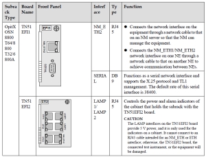
For OptiX OSN 8800/OptiX OSN 6800A, the NM_ETH1/NM_ETH2 interfaces on the
TN51ETH1/TN51ETH2/TN16EFI boards are used for achieving inter-NE communication. TheETH1, ETH2, and ETH3 interfaces on the TN51ETH2/TN16EFI boards are used to achieveintra-NE communication.Table 1 provides the correct connections of these networkinterfaces.
Table 1 Network cable interfaces
6-12 6800 11
6-12 6800 12
6-12 6800 13
6-12 6800 14
Connections
On a network where only OptiX OSN 8800 or OptiX OSN 6800A NEs are used, intra-NE and inter-NE communication are achieved through fiber connections and network cable connections.
NE Connections
Figure 1 and Figure 2 show the NE connection scheme. The figure presents connections
between two NEs: NE1 and NE2. Each NE consists of three subracks, one of which is the master subrack and the other two are slave subracks. The master and slave subracks are connected using fibers and network cables.
OptiX OSN 8800/6800A/3800A Installing, Operating and Maintaining Your Network(For
Field Engineer) 3 Quick View of Product Issue 02 (2013-10-30) Huawei Proprietary and Confidential Copyright © Huawei Technologies Co., Ltd. 314

Figure 1 NE connection scheme (OptiX OSN 8800 T32/8800 T64/6800A)
6-12 6800 15
Figure 2 NE connection scheme (OptiX OSN 8800 T16)
6-12 6800 16

Inter-NE communication:
l As shown in the figure above, NE1 connects to the NMS through the NM_ETH1 interface
on the EFI2/EFI board in the master subrack using a network cable, enabling the NMS to
manage the two NEs.
l Inside each NE, OTU, OADM/OA/OM/OD, OSC, and FIU boards are properly connected
through fibers. The FIU boards are also connected to other NEs. ESC or OSC channels are used to achieve inter-NE communication.
l The NM_ETH2 interface on the EFI1/EFI board in the master subrack of one NE is
connected to the NM_ETH1 interface on the EFI2/EFI board inside the master subrack of
the other NE using a network cable, achieving inter-NE communication over Ethernet
channels.
Intra-NE communication:
For each NE, the ETH2 and ETH3 interfaces on the EFI2/EFI board inside the master subrack are connected to the ETH1 interfaces on the EFI2/EFI boards in the slave subracks to achieve communication between the subracks.

Management Connections among OSN8800&6800A&3800A
On a hybrid network where OptiX OSN 8800, 6800A, and 3800A NEs are used, the inter-NE communication and intra-NE communication are achieved through fiber connections and network cable connections.
Connections
Figure 3 shows the NE connection scheme. The figure illustrates how three NEs (namely
NE1, NE2, and NE3) of different types are connected. As shown in the figure, NE1 consists of a master subrack (OptiX OSN 8800) and two slave subracks (OptiX OSN 8800 T16/6800A); NE2 and NE3 are two OptiX OSN 3800A NEs.
Figure 3 NE connection scheme
6-12 6800 17
Inter-NE communication:
l As shown in the figure above, NE1 connects to the NMS through the NM_ETH1 interface
on the EFI2 board in the master subrack using a network cable, enabling the NMS to manage all the NEs.
l The OTU, OADM/OA/OM/OD, OSC, and FIU boards inside NE1 are connected through
fibers. The FIU boards are also connected to other NEs. ESC or OSC channels are used to achieve inter-NE communication.
l NE2 and NE3 are connected through their OTU, OADM/OA, OSC, and FIU boards using
fibers. The FIU boards of the two NEs are also connected to other NEs. ESC or OSC
channels are used to achieve inter-NE communication.
l The NM_ETH2 interface on the EFI1 board of the master subrack inside NE1 connects to
the NM_ETH1 interface on the AUX board inside NE2 through a network cable. The
NM_ETH2 interface on the AUX board inside NE2 also uses a network cable to connect
to the NM_ETH1 interface on the AUX board inside NE3. In this manner, all the NEs
communicate with each other using Ethernet channels.
Intra-NE communication:
For NE1, the ETH2 and ETH3 interfaces on the EFI2 board inside the master subrack are
connected to the ETH1 interfaces on the EFI2/EFI boards in the slave subracks to achieve
communication between the subracks.

Telephone: 852-30623083
           Supports@Thunder-link.com